Cavity Drain R7 is manufactured from 0.5mm translucent high density polyethylene with studs approximately 7mm high. Other systems are available for specific uses, refer to Typical Uses inside.
Benefits
- Easy to install
- High drainage capacity
- High factor of safety
- High compressive strength
- Chemically resistant
- Can be applied to wet substrates
Applications
- Basement and Sub-structures
Applied to
- Concrete
- Masonry
Typical Uses
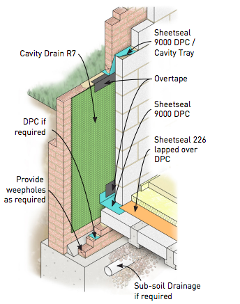
Cavity Drain R7 is used in situations where site conditions or structural design make it difficult or impossible to use traditional tanking methods. Cavity Drain R7 is used to collect water entering the structure and channel it to a sump or collection point for disposal (see details).
Cavity Drain R7 is suitable for use on floors and ceilings, please consult RIW for further information/ guidance.
When designing Type C structures (drained) protection, as classified in BS 8102: 2009, the product applied correctly, is capable of providing the levels of protection required for Grade 1, 2 & 3 basements.
The product can also be used in conjunction with Type A or B protection where additional combined protection is required.
Other systems available are:
Cavity Drain R20 - suitable for use on floors and vertically where a larger drainage capacity system is required.
Plaster Drain - suitable for use where walls are to be finished with a plaster or render.
Durability
Subject to normal conditions of use Cavity Drain R7 will provide an effective barrier to the transmission of water and water vapour for the life of the structure.
Specification
J40-Sheet Tanking/Damp Proofing in accordance with NBS Clause 290. Please consult RIW for further information.
Independent Authority
Cavity Drain R7 has been awarded British Board of Agrément Certificate No. 05/4232, covering its use on walls, floors and ceilings above and below ground.
Performance & Composition
| Form | HDPE profiled sheet |
| Colour | Translucent |
| Thickness | 0.5mm |
| Stud height | 6.5mm |
| Roll size | 2.07m* wide x 20m long |
| Weight | 0.48kg/m2 |
Laps - Side | 70mm |
Maximum drainage capacity | 3.8 litres/sec/metre length |
Working temperature | -10˚C to 60˚C |
Maximum compressive strength | 150kN/m2 |
* Includes dome free area for overlapping rolls. The above performance figures are typical values and should not be considered a product specification.
Ancillary Products
RIW produce a range of ancillary products for use with Cavity Drain R7 which include:
Sealing Rope - a self-adhesive rope for sealing around services, fixings etc.
Brick Plugs - a fixing plug for vertical fixing of the Cavity Drain.
Overtape - a self-adhesive tape used to seal over joints, when necessary.
Sealing Tape - a self-adhesive tape for sealing between flanged overlaps.
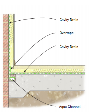
Aqua Channel - an internal peripheral drainage channel for use at the base of the wall.
Sump and pumps also available; see separate data.
Construction
General
All construction should conform with the Building Regulations, Codes of Practice and British Standards in current use at the time the building is being constructed. In particular it is recommended that reference is made to BS 8102: 2009.
Preparation
All surfaces: Should be firm, and free from obstructions, which would hamper free drainage. Defects that might result in unacceptable leaks should be remedied before the system is installed.
Concrete surfaces: Should be treated with Cementseal Primer to reduce the risk of leaching of free lime or mineral salts, and to avoid the obstruction of the drainage system.
Application
Vertical: Installation of the Cavity Drain R7 is ideally commenced at the top of the construction. The lower sheet is always positioned in front of the upper sheet, to form a ‘weathered lap’. Fixings: Should be made, using Brick Plugs, into 10 mm diameter drilled holes to a minimum depth of 75mm (use punch).
Fixings are sealed with Sealing Rope, which is packed around the brick plug before positioning. The fixings are normally required at 1.0m centres, and should be staggered. Fixings are also required immediately either side of the laps.
Overlaps: Flanged edges should always be positioned in front of, and overlapping, the previously installed membrane width. Laps with flanged edges are sealed using Sealing Tape, and laps without flanges are interlocked with the outer edge covered with Overtape.
Wall/floor junctions: Incorporate Aqua Channel as per typical details.
Service penetrations: The Cavity Drain R7 should be cut so it forms a butt joint against any projections, and then sealed with Sealing Rope. The surface should then be cleaned prior to application of Overtape around the penetration.
Protection: Vertical surfaces should be protected, by dry lining or by building an inner masonry wall against the Cavity Drain R7. Inner masonry walls may be tied back into the Cavity Drain R7, by fixing into the Brick Plugs. A similar method can be adopted should a ‘dry lining’ system be required.
Any damaged areas must be repaired, by cutting a patch at least 200mm larger than the damaged area. The patch is then overlaid and the edges sealed using Overtape as elsewhere.
Drainage: A drainage system of suitable capacity should be provided to collect and dispose of the infiltrating water. The system must be maintainable and inspected at regular intervals.
Supply
Availability
All products can be obtained through Builders Merchants or approved stockists. A list of approved stockists is available from RIW’s offices.
Packaging
Cavity Drain R7 | 2.07m wide x 20m long |
| Brick Plugs | Box of 100 |
| Sealing Rope | 10mm diameter x 5m long rolls |
| Sealing Tape | 30 x 2mm x 20m long rolls |
| Overtape | 150mm wide x 10m long rolls |
| Aqua Channel | 2m Lengths |
Storage
There are no special requirements but rolls should be kept upright under cover and protected from extremes of temperature.
Technical Services
The Technical Department is available to advise on individual projects and to prepare or assist in the preparation of specifications and drawings. A list of experienced applicators of our materials is available from RIW’s offices.
The information in this literature was correct at the time of going to press. However, we are committed to continually improving our products and reserve the right to change product specifications.
For the latest information, please consult RIW. Conditions of use are beyond our control, therefore we cannot warrant the results to be obtained.
Download
Click here to download this information in PDF format.


